Difference between revisions of "Filament model"
| (2 intermediate revisions by the same user not shown) | |||
| Line 54: | Line 54: | ||
# randomlly distributed in the tube of the filament. | # randomlly distributed in the tube of the filament. | ||
| − | + | [[File:filamentTypes.png|thumb|center|upright|800px|Crop positions generated by the different filament types. The central points are common in all types. Matlab syntax can be consulted [[Filament types code example here]] ]] | |
| − | [[File:filamentTypes.png|thumb|center|upright|800px|Crop positions generated by the different filament types. The central points are common in all types.]] | ||
====<tt>filamentWithTorsion</tt>==== | ====<tt>filamentWithTorsion</tt>==== | ||
| Line 61: | Line 60: | ||
Parameters: | Parameters: | ||
| − | * <tt>subunits_dz</tt> distance of the subunits along the backbone (in pixels) | + | * <tt>subunits_dz</tt> distance of the subunits along the backbone (in pixels). |
| − | *<tt> subunits_dphi</tt> torsion between subunits (in degrees). | + | *<tt> subunits_dphi</tt> torsion between subunits (in degrees). |
====<tt>filamentSubunitsOnHelix</tt>==== | ====<tt>filamentSubunitsOnHelix</tt>==== | ||
| Line 69: | Line 68: | ||
Parameters: | Parameters: | ||
| − | * <tt> | + | * <tt> subunits_dz </tt> distance of the subunits along the backbone (in pixels). |
| − | * <tt> | + | * <tt> subunits_dphi </tt> angular distance between the subunits (in degrees) . |
| − | * <tt>radius</tt> distance of the subunits to the backbone (in pixels) | + | * <tt>radius</tt> distance of the subunits to the backbone (in pixels). |
| + | |||
| + | ====<tt>filamentSubunitsOnRings</tt>==== | ||
| + | |||
| + | Several equally spaced rings of subunits are distributed along the path of the filament. | ||
| + | |||
| + | Parameters: | ||
| + | * <tt> ringSeparation </tt> in pixels. | ||
| + | * <tt> subunitsPerRing </tt> | ||
| + | * <tt>radius</tt> distance of the subunits to the backbone (in pixels). | ||
=== Computation of the particles === | === Computation of the particles === | ||
| Line 94: | Line 102: | ||
: uses the geometrical parameters of the model: <tt>dz</tt>, <tt>dphi</tt>, etc.... | : uses the geometrical parameters of the model: <tt>dz</tt>, <tt>dphi</tt>, etc.... | ||
* <tt>saveIntoCatalogue</tt> | * <tt>saveIntoCatalogue</tt> | ||
| + | |||
| + | The syntax for invoking these models can be consulted in this [[Filament types code example | matlab code example]] . | ||
Latest revision as of 15:29, 15 August 2016
Filament models are used for geometries where location and orientation of particles to be cropped (called subunitsin this context) can be defined with relation to tubular estructures.
The usual way of handling them is by opening a small fraction of a tomogram inside dtmslice and mark manually positions that will be used to define a "backbone". Loosely speaking, we call the "backbone of the filament" to the series of ordered points that arise from defining successive orthogonal sections along the path of the filament and picking the central point. Different models are available for the different relationships between the "backbone" of the filament and the locations and positions of the particles to be cropped.
Input stage
The input points in a filament model are used to define a smooth interpolant called backbone.
Clicking input points in dtmslice
A [video tutorial] explains with detail the process of picking points and converting them into subunit locations.
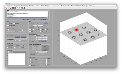
The basic tool for tracking filaments is dtmslice. In this tools, creating the points of a filament can be done manually in three steps:
- Select extremal points,
- Create orthogonal sections
- Click on the center of each section.
Select extremal points (anchors)
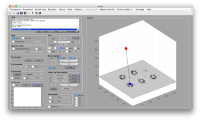
Click on [1] and [2] to select two extremal points in the filament, typically in two different sections. [1] will appear as a red diamond, [2] appears as a blue diamond.
Create orthogonal sections
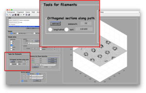
In the Filament Tools panel, you can select a partition of the space between the anchor points. The default value is 1:10:100, meaning: "divide the distance between the anchor points in 100 parts, and create an orthogonal section every 10 points".
You can also select a sidelength different to the default value of 32. Here, the units are pixels.
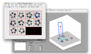
After clicking the [extract] button, two things will happen:
- An animation on the dtmslice scene will show the sections that will be extracted (using a small cyan rectangle).
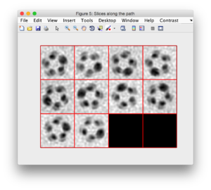
- The sections will appear as a montage in a new window.
Define section centers
In the currently released version, the user is asked to click on the the center of each shown section.
Geometric computation stage
The manually introduced points need to be converted into particle points.
Types of filaments
Different models are provided to account for different ways of relating particles to the points provided by the user during the input stage:
- along the path
- helically distributed pointing outwards
- in rings orthogonal to the path, pointing outwards.
- randomlly distributed in the tube of the filament.

filamentWithTorsion
The subunits will be defined along the backbone. The center of each subunit will be defined in the backbone. The zdirection of the subunit is defined to be colineal with the orientation of backbone at that point, and the distance between two subsequent subunits is defined by the model parameter dz. The torsion effect referred to by the name of the model refers to the fact that the x direction of two subsequent subunits can be chosen to vary a fixed amount (with parameter dphi)
Parameters:
- subunits_dz distance of the subunits along the backbone (in pixels).
- subunits_dphi torsion between subunits (in degrees).
filamentSubunitsOnHelix
In this case, the subunits to be cropped are supposed to be located on a helix that turns along the backbone of the filament. The center of the subunits is on a fixed distance from the backbone of the filament (defined by parameter radius), and the z direction points radially from the backbone, while x points along the way of the filament.
Parameters:
- subunits_dz distance of the subunits along the backbone (in pixels).
- subunits_dphi angular distance between the subunits (in degrees) .
- radius distance of the subunits to the backbone (in pixels).
filamentSubunitsOnRings
Several equally spaced rings of subunits are distributed along the path of the filament.
Parameters:
- ringSeparation in pixels.
- subunitsPerRing
- radius distance of the subunits to the backbone (in pixels).
Computation of the particles
Using a workflow tool
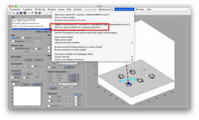
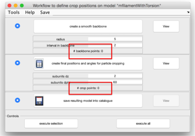
The Active model option in dtmslice includes the option Step-by-step workflow for model.
Programmatically
The methods used for the processing of a filament objects are typically:
- createBackbone
- derives a smooth backbone that interpolates the points introduced by the user.
- normally does not require to change any parameter.
- updateCrop
- creates the crop_points and crop_angles corresponding to the particular model.
- uses the geometrical parameters of the model: dz, dphi, etc....
- saveIntoCatalogue
The syntax for invoking these models can be consulted in this matlab code example .
