Difference between revisions of "Dipole set models"
| (2 intermediate revisions by the same user not shown) | |||
| Line 13: | Line 13: | ||
=== Sets of vesicles === | === Sets of vesicles === | ||
| − | Each dipole has four points available, which can be used with full flexibility as geometrical markers. We frequently use the <tt>north</tt> and the <tt>center</tt> to mark vesicular entities in a given tomogram (each dipole being a separate vesicle, and using a single <tt>dipole set<tt> model to encompass all the models). Some manipulation [[Vesicle_models#From_dipole_set_models | from the command line ]] allows then to create a real <tt>vesicle</tt> model for ach dipole in the dipole set model. | + | Each dipole has four points available, which can be used with full flexibility as geometrical markers. We frequently use the <tt>north</tt> and the <tt>center</tt> to mark vesicular entities in a given tomogram (each dipole being a separate vesicle, and using a single <tt>dipole set</tt> model to encompass all the models). Some manipulation [[Vesicle_models#From_dipole_set_models | from the command line ]] allows then to create a real <tt>vesicle</tt> model for ach dipole in the dipole set model. |
== Edition in <tt>dtmslice</tt> == | == Edition in <tt>dtmslice</tt> == | ||
| Line 20: | Line 20: | ||
The points on the currently dipole appear bigger than in the other dipoles. The current dipole has a green square selection mark, so that you can see it while it is ocluded by other elements in the scene (like the tomogram slice). A dipole that comprises the <tt>center</tt> and at least other point will be shown inside a transparent enclosing sphere. If this sphere shadows the dipole, you can secondary click on it and then press the option to hide the graphical depiction. When the enclosing sphere is not visible, you can secondary click on the dipole itself to delete it. | The points on the currently dipole appear bigger than in the other dipoles. The current dipole has a green square selection mark, so that you can see it while it is ocluded by other elements in the scene (like the tomogram slice). A dipole that comprises the <tt>center</tt> and at least other point will be shown inside a transparent enclosing sphere. If this sphere shadows the dipole, you can secondary click on it and then press the option to hide the graphical depiction. When the enclosing sphere is not visible, you can secondary click on the dipole itself to delete it. | ||
| − | |||
=== Select points in the current dipole === | === Select points in the current dipole === | ||
| Line 76: | Line 75: | ||
You can also click on [>], which moves a dipole up without the popup window. It just creates a message in the information window of <tt>dtmslice</tt>. You can always click on [?] to get a readout on which dipole number is the current one inside the dipole set. | You can also click on [>], which moves a dipole up without the popup window. It just creates a message in the information window of <tt>dtmslice</tt>. You can always click on [?] to get a readout on which dipole number is the current one inside the dipole set. | ||
| − | [[File: | + | [[File:DipoleVesicleExampleNewDipoleMessage.png|thumb|center|400px| Information window in <tt>dtmslice</tt> reports the number of the current dipole, i.e., the one in which the clicks on [c],[n],[s] and [w] will be assigned.]] |
You can create now a new dipole. Note that now the current dipole number is two: this dipole appears represented with bigger marks, and with a selection mark (two floating squares). | You can create now a new dipole. Note that now the current dipole number is two: this dipole appears represented with bigger marks, and with a selection mark (two floating squares). | ||
Latest revision as of 17:20, 24 February 2017
The dipole set model allows to gather sets of dipoles, each one being an assemble of 3d points called center,north, south and west. Not every point needs to be defined.
When a table is extracted from a dipole set model, each dipole will define a separate particle (i.e., a row in the table). The cropping points will be located each on the center property of each dipole. The cropping angles will be computed so that z direction of the particle is colinear with the north to center axis of the dipole. I a west point is present, the west to center axis will define the x axis of the particle.
The qualified name of the model class in dmodels.dipoleSet.
Contents
Applications
Oriented particles
Sometimes it is useful to be able to directly collect the orientation of the particle from a simple interaction with the tomogram (obviously only for particles with a clearly identifiable directionality). For large data sets, it is not advisable to try to click all your particles with this model: the way we normally use it is to collect moderate numbers of particles (in the order of magnitude of the tenths) to construct an initial reference.
Sets of vesicles
Each dipole has four points available, which can be used with full flexibility as geometrical markers. We frequently use the north and the center to mark vesicular entities in a given tomogram (each dipole being a separate vesicle, and using a single dipole set model to encompass all the models). Some manipulation from the command line allows then to create a real vesicle model for ach dipole in the dipole set model.
Edition in dtmslice
Dipole set can be defined on screen in the dtmslice volume browser. When the active model is of type dipole set , a number of keyboard controls are activated. The procedure is to input (some of) the points that define a dipole and then pass to the next one.
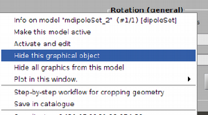
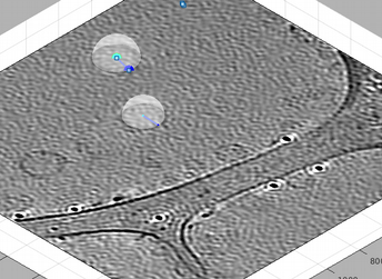
The points on the currently dipole appear bigger than in the other dipoles. The current dipole has a green square selection mark, so that you can see it while it is ocluded by other elements in the scene (like the tomogram slice). A dipole that comprises the center and at least other point will be shown inside a transparent enclosing sphere. If this sphere shadows the dipole, you can secondary click on it and then press the option to hide the graphical depiction. When the enclosing sphere is not visible, you can secondary click on the dipole itself to delete it.
Select points in the current dipole
- [c] creates or shifts the center point in the current dipole (cyan).
- [n] creates or shifts the north point in the current dipole (blue).
- [s] creates or shifts the south point in the current dipole (red).
- [w] creates or shifts the west point in the current dipole (magenta).
While you remain in the same dipole, pressing any of this keys will redefine the corresponding point.
Change current dipole
- [<] or [leftarrow] Moves the current dipole one down.
- [n] or [rightarrow] Moves one current dipole one up.
- [enter] opens a new, empty dipole and makes it active.
- If the dipole with the highest label is empty, it makes it active, instead of creating a new one.
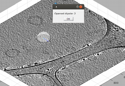
- It briefly shows a window announcing the label of the created dipole.
- [?] Writes the labels of the dipoles that have been defined.
Walkthrough
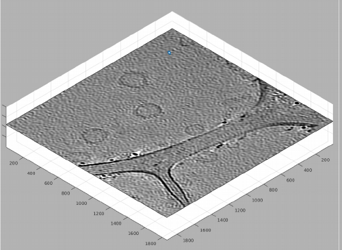
We show a step by step walkthrough on the use of the dipole set controls inside dtmslice.
Consider a single tomogram containing several vesicles. We want to define a single dipole set model, and capture each vesicle as a different dipole, by picking the center of the vesicle, and then one point as the north of the dipole, which will later define the radius of the vesicle.
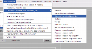
We create first a dipole set model, which automatically becomes active. Whenever the active model if of dipoleSet class, the keyboard shortcuts for dipole sets are working.
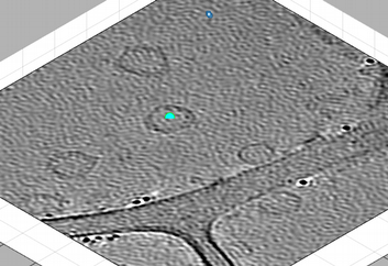
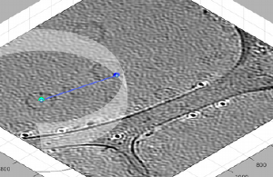
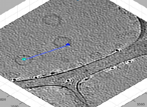
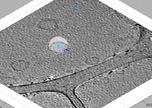
We can then use [C] and [N] to mark the center and north points. The second one should create a transparent sphere enclosing the dipole.
New clicks on [C],[N],[S],or [W] will be referred to the current dipole. If you forget to open a new dipole and click one of them, you will just mess the dipole you just created. In this example, if you just click [C] on the center of the vesicle on the left, you will just move the current center.
If something like this happens you need to move the point [C] to its right position. You may need to hide the transparent spheres for this, y secondary clicking on one sphere and then selecting the option.
Ok, we solved the problem. Now, in order to proceed you need to click on [enter]. This will briefly announce with a popup window that a new dipole has been opened.
You can also click on [>], which moves a dipole up without the popup window. It just creates a message in the information window of dtmslice. You can always click on [?] to get a readout on which dipole number is the current one inside the dipole set.
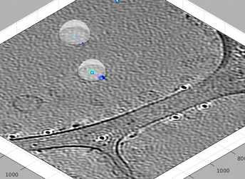
You can create now a new dipole. Note that now the current dipole number is two: this dipole appears represented with bigger marks, and with a selection mark (two floating squares).
You can move the current selected dipole up and down with the [<] and [>] keys, or with the left and right arrows.
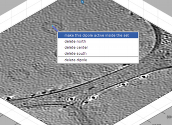
Also, after hiding the enclosing spheres, you can secondary click on one the lines that define the dipole, and get a menu of options. This allows you to delete the individual dipole or to make it current.
