Difference between revisions of "Walkthrough model worfklow reuse"
| Line 12: | Line 12: | ||
{|style="margin: 0 auto;" | {|style="margin: 0 auto;" | ||
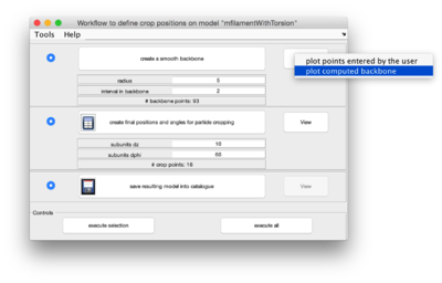
| − | | [[File:ReuseWorkflowBackbonePlotOrder.png|thumb|upright|400px| | + | | [[File:ReuseWorkflowBackbonePlotOrder.png|thumb|upright|400px| right click to get the plotting options of a step ]] |
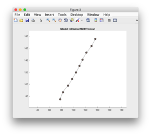
| − | | [[File:ReuseWorkflowBackbonePlot.png|thumb|upright| | + | | [[File:ReuseWorkflowBackbonePlot.png|thumb|upright|300px|created backbone traversing the <tt>points</tt> ]] |
|} | |} | ||
We then proceed for the next step: selection of the interval (in pixels) between two consecutive crop points. | We then proceed for the next step: selection of the interval (in pixels) between two consecutive crop points. | ||
Revision as of 05:10, 17 August 2016
This walkthrough shows how to reuse the geometric computations performed on a single model onto a larger set of models.
We can use a synthetic tomogram containing different tubular structures. In this catalogue, we open the tomogram with dtmslice, and then define a filament model following the usual procedure, so that we end up with a single model containing a set on points.
We will now define a workflow, i.e., a method of converting points into crop_points.
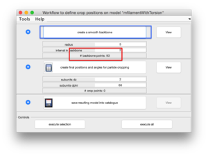
We open the workflow editor of the active model, and start operating the steps, checking graphically the result of each parameter selection. We create first a backbone, selecting the interval between backbone elements.
And check how the results looks like.
We then proceed for the next step: selection of the interval (in pixels) between two consecutive crop points.


